

『Schematic diagram of electromagnetic flowmeter』Related information(v cone flow meter|rotary gas meter|gallon meter|gear meter|metal tube rotameter|glass tube rotameter|nutating disk meter|transit time ultrasonic flow meter|wedge flow meter|pd meters|hydraulic flow meter|ultrasonic water flow meter|water flow meter|air flow meter|magnetic water flow meter|oxygen flow meter|gas flow meter|argon flow meter|air velocity meter|gasoline flow meter|fuel flow meter|ultrasonic water meter|digital water meter|nitrogen flow meter|solid flow meter|Oxygen tank flow meter|digital water flow meter|diesel fuel flow meter|steam flow meter|02 flow meter|compressed air flow meter|oil flow meter|liquid flow meter)

1. What is the working principle of an electromagnetic flowmeter? The working principle of an electromagnetic flowmeter is based on Faradays law of electromagnetic induction, which calculates flow velocity and flow rate by measuring the induced electromotive force generated by the motion of a conductive fluid in a magnetic field. 1. Core principle: When a conductive fluid (such as water, acid, alkali, slurry, etc.) flows through a stable magnetic field generated by an excitation coil, the fluid acts as a moving conductor and cuts magnetic induction lines. According to Faradays law of electromagnetic induction, an induced seepage electromotive force (E) will be generated in a direction perpendicular to both the magnetic field and the fluid flow direction. Its size can be represented by the formula E=k B D v, where: • E: induced electromotive force (V) • k: instrument constant • B: magnetic induction intensity (T) • D: inner diameter of the measuring tube (m) • v: average flow velocity of the fluid (m/s) 2. System composition: An electromagnetic flowmeter is mainly composed of the following four parts: • Measuring tube: It is lined with insulating materials (such as polytetrafluoroethylene, rubber) to prevent the induced electromotive force from being short circuited. Excitation system: composed of a pair of excitation coils, used to generate a stable or alternating magnetic field. Electrode: Typically a pair of metal electrodes installed tightly against the inner lining, used to detect the induced electromotive force generated by the fluid. • Converter: The core signal processing unit amplifies, filters, and calculates the weak voltage signal detected by the electrode, and finally converts it into a standard flow sign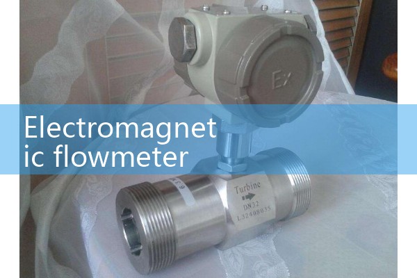
2. Open channel radar flowmeter
3. Principle of electromagnetic flowmeter
The basic principle of electromagnetic flowmeter is based on Faradays law of electromagnetic induction, and its core is to calculate the fluid volume flow rate by measuring the induced electromotive force generated by the movement of conductive fluid in a magnetic field.
. The specific principle is as follows:1. The core function of Faradays law of electromagnetic induction is that when a conductor (such as a conductive fluid) cuts magnetic field lines in a vertical direction, an induced electromotive force proportional to the velocity and magnetic field strength will be generated inside the conductor. The formula is expressed as: E=B × L × vE: induced electromotive force (voltage) B: magnetic field strength (Tesla) L: electrode spacing (conduit diameter) v: average fluid flow velocity (meters/second). This relationship is the theoretical basis for measuring flow rate with an electromagnetic flowmeter. Electrode installation: Install a pair of electrodes on both sides of the inner wall of the conduit (insulated lining), with the electrode wires perpendicular to both the conduit axis and the magnetic field direction. Insulation lining: The inner wall of the conduit is made of insulation materials (such as rubb
 Hot Product
 Related AD